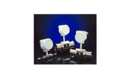
Thermal In-Line Flowmeter Model 600-9UHP
Unobstructed Flow-Accurate, Reliable Measurements. No Fluid Contact with the
Sensor. No Obstruction in the Flow Path.
True Mass Flow Signal in Weight &Time. Unobstructed Straight Flow Tube. 316L,
Low Sulfur Stainless Steel Materials. All Welded, Non-Oxidizing Construction. "
CIP/SIP" Clean in Place Design. Excellent for Flow Switch Applications with Field
Adjustable Form C Relay Switch Points. Range Capability to 100:1 with
Accurate Low Flow Pure Performance. 15RA Finish for Ultra pure Design.
Sanitary Design Exceeds Grit Finish Standards. Tri-Clamp, VCR, VCO and Stub
Weld Process Connections.

Accuracy: 0.5% of Full Scale or 2% of reading - whichever is better
Repeatability: Better than 0.2% of reading
Process Fluid Temperature Range:
STD: -40°F to 350°F (-40°C to 177°C)
OPT: -250°F to 1100°F (-156°C to 593°C)
Process Fluid Pressure Range:
STD: 0 - 1,200 PSIG (0 to 84 kg/cm2)
OPT: 0 - 60,000 PSIG (0 to 4,220 kg/cm2)
Hazardous Areas:
Designed to CE and X-Proof
CLI Group B, C, D, Div 1, 2
Output: From Signal Converter, Isolated Analog 4 - 20 Madc into 1,000 OHMS

• TUBE END CONSTRUCTION DIMENSION CHART [PDF]
• VCR MALE CONSTRUCTION DIMENSION CHART [PDF]
• VCR FEMALE CONSTRUCTION DIMENSION CHART [PDF]